|
|
|||||||||||||||||||
|
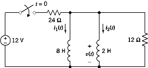
P 7.7-8 The circuit shown in Figure P 7.7-8 is at steady state before
the switch closes. The inductor currents are both zero before the switch
closes (i1(0)
= i2(0) = 0). |
|||||||||||||||||||
|
The voltage
is given by |
|||||||||||||||||||
|
|
|||||||||||||||||||
|
(a) Determine the inductor currents, i1(t) and i2(t), for t ≥
0. |
|||||||||||||||||||
|
(b) Determine the energy stored by each inductor 200 ms after the switch closes. |
|||||||||||||||||||
|
The
parallel inductors can be replaced by an equivalent inductor. |
|||||||||||||||||||
|
(c) Determine the current in the equivalent inductor, directed
downward, for |
|||||||||||||||||||
|
(d) Determine the energy stored in the equivalent inductor 200 ms after the switch closes. |
|||||||||||||||||||
|
|
|||||||||||||||||||
|
|
|||||||||||||||||||
|
Figure P 7.7-8 |
|||||||||||||||||||
|
|
|||||||||||||||||||
|
(a) Determine
the inductor currents, i1(t) and i2(t), for t ≥
0. |
|||||||||||||||||||
|
|
|||||||||||||||||||
|
Since we know v(t), we can get
i2 from |
|||||||||||||||||||
|
|
|||||||||||||||||||
|
|
|||||||||||||||||||
|
We are told |
|||||||||||||||||||
|
|
|||||||||||||||||||
|
|
|||||||||||||||||||
|
|
|||||||||||||||||||
|
|
|||||||||||||||||||
|
|
|||||||||||||||||||
|
Now since the other inductor
is in parallel it sees the same voltage so |
|||||||||||||||||||
|
|
|||||||||||||||||||
|
|
|||||||||||||||||||
|
|
|||||||||||||||||||
|
Again we were told |
|||||||||||||||||||
|
|
|||||||||||||||||||
|
|
|||||||||||||||||||
|
|
|||||||||||||||||||
|
|
|||||||||||||||||||
|
|
|||||||||||||||||||
|
(b) Determine
the energy stored by each inductor 200 ms after the
switch closes. |
|||||||||||||||||||
|
|
|||||||||||||||||||
|
Use expression |
|||||||||||||||||||
|
|
|||||||||||||||||||
|
so |
|||||||||||||||||||
|
|
|||||||||||||||||||
|
|
|||||||||||||||||||
|
|
|||||||||||||||||||
|
and |
|||||||||||||||||||
|
|
|||||||||||||||||||
|
|
|||||||||||||||||||
|
|
|||||||||||||||||||
|
|
|||||||||||||||||||
|
Now let t = 0.200s |
|||||||||||||||||||
|
|
|||||||||||||||||||
|
|
|||||||||||||||||||
|
|
|||||||||||||||||||
|
|
|||||||||||||||||||
|
|
|||||||||||||||||||
|
The parallel inductors can be replaced by an
equivalent inductor. |
|||||||||||||||||||
|
|
|||||||||||||||||||
|
The inductors are in parallel
so |
|||||||||||||||||||
|
|
|||||||||||||||||||
|
|
|||||||||||||||||||
|
|
|||||||||||||||||||
|
|
|||||||||||||||||||
|
|
|||||||||||||||||||
|
(c)
Determine the current in the equivalent inductor, directed downward, for |
|||||||||||||||||||
|
|
|||||||||||||||||||
|
|
|||||||||||||||||||
|
|
|||||||||||||||||||
|
Again |
|||||||||||||||||||
|
|
|||||||||||||||||||
|
|
|||||||||||||||||||
|
|
|||||||||||||||||||
|
|
|||||||||||||||||||
|
|
|||||||||||||||||||
|
As would be
expected. |
|||||||||||||||||||
|
|
|||||||||||||||||||
|
(d) Determine
the energy stored in the equivalent inductor 200 ms
after the switch closes. |
|||||||||||||||||||
|
|
|||||||||||||||||||
|
|
|||||||||||||||||||
|
|
|||||||||||||||||||
|
So at 0.2 s |
|||||||||||||||||||
|
|
|||||||||||||||||||
|
|
|||||||||||||||||||
|
|
|||||||||||||||||||
|
|
|||||||||||||||||||
|
As it should! |
|||||||||||||||||||
|
|
|||||||||||||||||||
|
|||||||||||||||||||
|
|
|||||||||||||||||||
|
|
|||||||||||||||||||
|
|||||||||||||||||||
|
|