|
|
|||||||||||||||||||
|
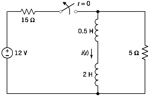
P 7.7-9 The circuit shown in Figure P 7.7-9 is at steady state before
the switch opens at time t = 0. |
|||||||||||||||||||
|
The current
is given by |
|||||||||||||||||||
|
|
|||||||||||||||||||
|
(a) Determine the energy stored by each inductor before the switch
opens. |
|||||||||||||||||||
|
(b) Determine the energy stored by each inductor 200 ms after the switch opens. |
|||||||||||||||||||
|
The
series inductors can be replaced by an equivalent inductor. |
|||||||||||||||||||
|
(c) Determine the energy stored by the equivalent inductor before
the switch opens. |
|||||||||||||||||||
|
(d) Determine the energy stored by the equivalent inductor 200 ms after the switch opens. |
|||||||||||||||||||
|
|
|||||||||||||||||||
|
|
|||||||||||||||||||
|
Figure P 7.7-9 |
|||||||||||||||||||
|
|
|||||||||||||||||||
|
(a) Determine
the energy stored by each inductor before the switch opens. |
|||||||||||||||||||
|
|
|||||||||||||||||||
|
Before switch opens at t = 0, i(t) = 0.8 A and the energy stored is given by |
|||||||||||||||||||
|
|
|||||||||||||||||||
|
|
|||||||||||||||||||
|
|
|||||||||||||||||||
|
|
|||||||||||||||||||
|
|
|||||||||||||||||||
|
|
|||||||||||||||||||
|
|
|||||||||||||||||||
|
(b) Determine
the energy stored by each inductor 200 ms after the
switch opens. |
|||||||||||||||||||
|
|
|||||||||||||||||||
|
After switch opens at t = 0, |
|||||||||||||||||||
|
|
|||||||||||||||||||
|
|
|||||||||||||||||||
|
|
|||||||||||||||||||
|
At t = 200 ms
= 0.2 s |
|||||||||||||||||||
|
|
|||||||||||||||||||
|
|
|||||||||||||||||||
|
and |
|||||||||||||||||||
|
|
|||||||||||||||||||
|
|
|||||||||||||||||||
|
At t = 200 ms
= 0.2 s |
|||||||||||||||||||
|
|
|||||||||||||||||||
|
|
|||||||||||||||||||
|
|
|||||||||||||||||||
|
The series inductors can be replaced by an
equivalent inductor. |
|||||||||||||||||||
|
|
|||||||||||||||||||
|
|
|||||||||||||||||||
|
|
|||||||||||||||||||
|
(c)
Determine the energy stored by the equivalent inductor before the switch
opens. |
|||||||||||||||||||
|
|
|||||||||||||||||||
|
|
|||||||||||||||||||
|
|
|||||||||||||||||||
|
|
|||||||||||||||||||
|
As it should! |
|||||||||||||||||||
|
|
|||||||||||||||||||
|
(d) Determine
the energy stored by the equivalent inductor 200 ms
after the switch opens. |
|||||||||||||||||||
|
|
|||||||||||||||||||
|
|
|||||||||||||||||||
|
|
|||||||||||||||||||
|
At t = 200 ms
= 0.2 s |
|||||||||||||||||||
|
|
|||||||||||||||||||
|
|
|||||||||||||||||||
|
|
|||||||||||||||||||
|
|
|||||||||||||||||||
|
As it should! |
|||||||||||||||||||
|
|
|||||||||||||||||||
|
|||||||||||||||||||
|
|
|||||||||||||||||||
|
|
|||||||||||||||||||
|
|||||||||||||||||||
|
|