|
|
|||||||||||||||||||
|
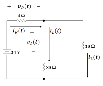
P 7.8-4 The switch in the circuit shown in Figure P 7.8-4 has been
closed for a long time before it opens at time t = 0. Determine the values of |
|||||||||||||||||||
|
|
|||||||||||||||||||
|
|
|||||||||||||||||||
|
Figure P 7.8-4 |
|||||||||||||||||||
|
|
|||||||||||||||||||
|
Here is an annotated circuit
from t<0 and in steady state |
|||||||||||||||||||
|
|
|||||||||||||||||||
|
In steady state the inductor
acts like a short circuit as drawn here, so the |
|||||||||||||||||||
|
|
|||||||||||||||||||
|
|
|||||||||||||||||||
|
|
|||||||||||||||||||
|
So the total resistance is 4Ω + 16 Ω
or 20 Ω. So the total current in steady state before
t = 0 is |
|||||||||||||||||||
|
|
|||||||||||||||||||
|
So |
|||||||||||||||||||
|
|
|||||||||||||||||||
|
|
|||||||||||||||||||
|
That means the voltage drops
over the 80 Ω
and the 20 Ω resistors are 24
V-4.8 V = 19.2 V so we can find the other two currents |
|||||||||||||||||||
|
|
|||||||||||||||||||
|
|
|||||||||||||||||||
|
And |
|||||||||||||||||||
|
|
|||||||||||||||||||
|
Check Current |
|||||||||||||||||||
|
|
|||||||||||||||||||
|
As it should. |
|||||||||||||||||||
|
After the switch is thrown
open, the circuit becomes: |
|||||||||||||||||||
|
|
|||||||||||||||||||
|
Now because of continuity conditions
on inductors we know |
|||||||||||||||||||
|
|
|||||||||||||||||||
|
|
|||||||||||||||||||
|
|
|||||||||||||||||||
|
Now |
|||||||||||||||||||
|
|
|||||||||||||||||||
|
|
|||||||||||||||||||
|
|
|||||||||||||||||||
|
To find |
|||||||||||||||||||
|
|
|||||||||||||||||||
|
|
|||||||||||||||||||
|
|
|||||||||||||||||||
|
|
|||||||||||||||||||
|
|
|||||||||||||||||||
|
|
|||||||||||||||||||
|
|
|||||||||||||||||||
|
|||||||||||||||||||
|
|
|||||||||||||||||||
|
|
|||||||||||||||||||
|
|||||||||||||||||||
|
|