|
|
|||||||||||||||||||
|
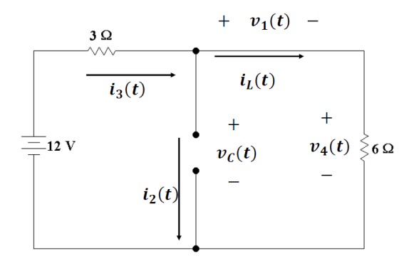
P 7.8-8 The circuit shown in Figure P 7.8-8 is at steady state when the
switch opens at time t = 0. Determine |
|||||||||||||||||||
|
|
|||||||||||||||||||
|
|
|||||||||||||||||||
|
Figure P 7.8-8 |
|||||||||||||||||||
|
Annotated Circuit from before
switch is opened |
|||||||||||||||||||
|
|
|||||||||||||||||||
|
At steady state
the inductor acts like a short circuit and the capacitor acts like an open
circuit. So we know immediately that |
|||||||||||||||||||
|
|
|||||||||||||||||||
|
|
|||||||||||||||||||
|
|
|||||||||||||||||||
|
|
|||||||||||||||||||
|
|
|||||||||||||||||||
|
So we have a simple series
circuit which means |
|||||||||||||||||||
|
|
|||||||||||||||||||
|
|
|||||||||||||||||||
|
|
|||||||||||||||||||
|
We can find |
|||||||||||||||||||
|
|
|||||||||||||||||||
|
|
|||||||||||||||||||
|
Now when the switch opens our
circuit becomes |
|||||||||||||||||||
|
|
|||||||||||||||||||
|
Since the left side of the
circuit is open, we know |
|||||||||||||||||||
|
|
|||||||||||||||||||
|
|
|||||||||||||||||||
|
We also know from continuity |
|||||||||||||||||||
|
|
|||||||||||||||||||
|
|
|||||||||||||||||||
|
And |
|||||||||||||||||||
|
|
|||||||||||||||||||
|
|
|||||||||||||||||||
|
Now because current in
inductor must be 4/3 A, we can find the voltage across the 6 Ω resistor |
|||||||||||||||||||
|
|
|||||||||||||||||||
|
|
|||||||||||||||||||
|
|
|||||||||||||||||||
|
Now we can do a voltage walk
to find the voltage across the inductor |
|||||||||||||||||||
|
|
|||||||||||||||||||
|
|
|||||||||||||||||||
|
|
|||||||||||||||||||
|
|
|||||||||||||||||||
|
|
|||||||||||||||||||
|
Finally current through
capacitor must be the same as the current in the inductor and the 6 Ω
resistor because we have a simple series loop. But since the current is going opposite to
the drawn reference direction we have |
|||||||||||||||||||
|
|
|||||||||||||||||||
|
|
|||||||||||||||||||
|
|
|||||||||||||||||||
|
So the answers are : |
|||||||||||||||||||
|
|
|||||||||||||||||||
|
|||||||||||||||||||
|
|
|||||||||||||||||||
|
|
|||||||||||||||||||
|
|||||||||||||||||||
|
|