|
|
|||||||||||||||||||
|
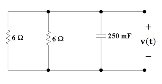
P 8.3-1 The circuit shown in Figure P 8.3-1 is at steady state before the switch closes at time t = 0. The input to the
circuit is the voltage of the voltage source, 12 V. The output of this
circuit is the voltage across the capacitor, v(t). Determine v(t) for t > 0. |
|||||||||||||||||||
|
|
|||||||||||||||||||
|
Answer: v(t) = 6 – 2e–1.33t V for
t > 0 |
|||||||||||||||||||
|
|
|||||||||||||||||||
|
|
|||||||||||||||||||
|
Figure
P 8.3-1 |
|||||||||||||||||||
|
|
|||||||||||||||||||
|
The General Solution is of the
Form: |
|||||||||||||||||||
|
|
|||||||||||||||||||
|
|
|||||||||||||||||||
|
|
|||||||||||||||||||
|
Where x is the variable we are
looking for usually voltage for a capacitor and current for an inductor. The “∞”
means the value of the variable after a long time, for voltage, this is usually
referred to as the “Open Circuit” voltage.
For current, this is usually referred to as
the “Short Circuit” current. Finally τ
is the appropriate time constant. For
a capacitor |
|||||||||||||||||||
|
|
|||||||||||||||||||
|
|
|||||||||||||||||||
|
For an inductor |
|||||||||||||||||||
|
|
|||||||||||||||||||
|
So for a capacitor, The
solution looks like: |
|||||||||||||||||||
|
|
|||||||||||||||||||
|
|
|||||||||||||||||||
|
|
|||||||||||||||||||
|
For |
|||||||||||||||||||
|
|
|||||||||||||||||||
|
Assuming the circuit is in
steady state, the voltage across the capacitor is the voltage across the
right 6 Ω resistor. Since there are 3 6 Ω resistors in series with the
capacitor acting like an open circuit, voltage division gives us |
|||||||||||||||||||
|
|
|||||||||||||||||||
|
|
|||||||||||||||||||
|
|
|||||||||||||||||||
|
After the switch is closed our
circuit becomes |
|||||||||||||||||||
|
|
|||||||||||||||||||
|
This time we only have two 6 Ω resistors in series, so doing
voltage division again we find that the long term voltage across the
capacitor is |
|||||||||||||||||||
|
|
|||||||||||||||||||
|
|
|||||||||||||||||||
|
|
|||||||||||||||||||
|
Deactivating power source so
we can calculate the Thevenin Resistance we get a
circuit |
|||||||||||||||||||
|
|
|||||||||||||||||||
|
So the Thevenin
resistance is two 6 Ω
resistors in parallel and |
|||||||||||||||||||
|
|
|||||||||||||||||||
|
|
|||||||||||||||||||
|
|
|||||||||||||||||||
|
So |
|||||||||||||||||||
|
|
|||||||||||||||||||
|
|
|||||||||||||||||||
|
Putting these values into our
standard form yields |
|||||||||||||||||||
|
|
|||||||||||||||||||
|
|
|||||||||||||||||||
|
simplifying |
|||||||||||||||||||
|
|
|||||||||||||||||||
|
|||||||||||||||||||
|
|
|||||||||||||||||||
|
|
|||||||||||||||||||
|
|||||||||||||||||||
|
|