|
|
|||||||||||||||||||
|
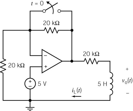
P 8.3-6 The circuit shown in Figure P 8.3-6 is at steady state before the switch opens at time t = 0. Determine the
voltage, vo(t), for t > 0. |
|||||||||||||||||||
|
|
|||||||||||||||||||
|
Answer: vo(t)
= 5e–4000t V for t
> 0 |
|||||||||||||||||||
|
|
|||||||||||||||||||
|
|
|||||||||||||||||||
|
Figure
P 8.3-6 |
|||||||||||||||||||
|
|
|||||||||||||||||||
|
With the switch closed the
equilibrium circuit for t < 0, The
closed switch shorts out the resistor and long term the inductor looks like a
short-circuit, so the annotated circuit looks like: |
|||||||||||||||||||
|
|
|||||||||||||||||||
|
Rules of ideal op-amps, mean
VA = 5 V and VB = 5 V also. Therefore,
iL is |
|||||||||||||||||||
|
|
|||||||||||||||||||
|
|
|||||||||||||||||||
|
|
|||||||||||||||||||
|
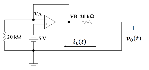
Once the switch opens the
annotated circuit looks like now: |
|||||||||||||||||||
|
|
|||||||||||||||||||
|
In this case, VA remains 5 V,
but now the current goes from ground up through the 20 kΩ resistor on the left. So clearly the
voltage across the 20 kΩ
resistor is 5 V. that
means as that current passes through the 20 kΩ
resistor on top, you must get another 5 V, since the current in that resistor
is going from left to right, VB now is +10 V!
This changes the current through the short circuit inductor is |
|||||||||||||||||||
|
|
|||||||||||||||||||
|
|
|||||||||||||||||||
|
and |
|||||||||||||||||||
|
|
|||||||||||||||||||
|
|
|||||||||||||||||||
|
|
|||||||||||||||||||
|
So the current through the
inductor is found from the general form |
|||||||||||||||||||
|
|
|||||||||||||||||||
|
|
|||||||||||||||||||
|
|
|||||||||||||||||||
|
|
|||||||||||||||||||
|
|
|||||||||||||||||||
|
The voltage across the
inductor is found from |
|||||||||||||||||||
|
|
|||||||||||||||||||
|
|
|||||||||||||||||||
|
|
|||||||||||||||||||
|
|
|||||||||||||||||||
|
|
|||||||||||||||||||
|
|||||||||||||||||||
|
|
|||||||||||||||||||
|
|
|||||||||||||||||||
|
|||||||||||||||||||
|
|