|
|
|||||||||||||||||||
|
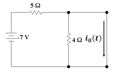
P 8.6-3 The input to
the circuit shown in Figure P 8.6-3 is the voltage of the voltage source, vs(t). The output is the current across
the inductor, io(t). Determine the output of this
circuit when the input is vs(t) = – 7 + 13 u(t) V. |
|||||||||||||||||||
|
|
|||||||||||||||||||
|
|
|||||||||||||||||||
|
Figure
P 8.6-3 |
|||||||||||||||||||
|
|
|||||||||||||||||||
|
For the time t < 0 the
power supply is providing a constant -7 V and the steady state circuit will
have the inductor acting like a short circuit as shown |
|||||||||||||||||||
|
|
|||||||||||||||||||
|
The current is going to be
just the current created by a simple series circuit of the -7 V and a 5 Ω resistor in series as the 4 Ω resistor is shorted out. So |
|||||||||||||||||||
|
|
|||||||||||||||||||
|
|
|||||||||||||||||||
|
|
|||||||||||||||||||
|
For the time t > 0 the power supply is now providing +6 V and again
the steady state circuit will have the inductor again acting like a short
circuit. |
|||||||||||||||||||
|
|
|||||||||||||||||||
|
Similarly we find the current
long term to be |
|||||||||||||||||||
|
|
|||||||||||||||||||
|
|
|||||||||||||||||||
|
|
|||||||||||||||||||
|
The Thevenin
resistance is going to be the 5 Ω
and the 4 Ω resistors in parallel
once you deactivate the power supply. So
|
|||||||||||||||||||
|
|
|||||||||||||||||||
|
|
|||||||||||||||||||
|
|
|||||||||||||||||||
|
Using the standard formula |
|||||||||||||||||||
|
|
|||||||||||||||||||
|
|
|||||||||||||||||||
|
|
|||||||||||||||||||
|
|
|||||||||||||||||||
|
|
|||||||||||||||||||
|
|||||||||||||||||||
|
|
|||||||||||||||||||
|
|
|||||||||||||||||||
|
|||||||||||||||||||
|
|