|
|
|||||||||||||||||||
|
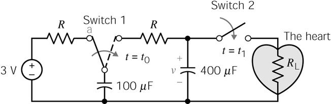
P 8.4-3 Cardiac pacemakers are used by people to maintain regular heart rhythm
when they have a damaged heart. The circuit of a pacemaker can be represented as shown in Figure P 8.4-3. The
resistance of the wires, R, can be
neglected since R < 1 mΩ. The heart’s load resistance, RL, is 1 kΩ. The first switch is activated at t = t0, and the second
switch is activated at t1
= t0 + 10 ms. This cycle is repeated every second. Find v(t) for t0 ≤ t
≤ 1. Note that it is easiest to consider t0 = 0 for this calculation. The cycle repeats by
switch 1 returning to position a and switch 2
returning to its open position. |
|||||||||||||||||||
|
|
|||||||||||||||||||
|
Hint: Use q
= Cv to
determine v(0–)
for the 100-μF capacitor. |
|||||||||||||||||||
|
|
|||||||||||||||||||
|
|
|||||||||||||||||||
|
Figure
P 8.4-3 |
|||||||||||||||||||
|
|
|||||||||||||||||||
|
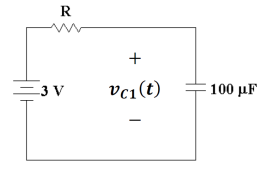
Prior to time t0,
whether it is 0 or not, if the circuit is in steady state, then it looks like
|
|||||||||||||||||||
|
|
|||||||||||||||||||
|
The capacitor is assumed to be fully charged and acting like an open
circuit so there is no current flowing through R. The voltage across the capacitor must equal
the power source or |
|||||||||||||||||||
|
|
|||||||||||||||||||
|
|
|||||||||||||||||||
|
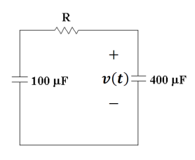
At t = t0 Switch 1 flips and we have the circuit |
|||||||||||||||||||
|
|
|||||||||||||||||||
|
Now the charge on the 100 µF capacitor when it is charged to 3
V before it is connected to the 400 µF
capacitor can be found from |
|||||||||||||||||||
|
|
|||||||||||||||||||
|
|
|||||||||||||||||||
|
|
|||||||||||||||||||
|
Now when the two capacitors
are joined in parallel, their new combined capacitance is |
|||||||||||||||||||
|
|
|||||||||||||||||||
|
|
|||||||||||||||||||
|
|
|||||||||||||||||||
|
There is a fixed amount of
charge (300 µC)
so the voltage resulting from the charge rearranging is found from |
|||||||||||||||||||
|
|
|||||||||||||||||||
|
|
|||||||||||||||||||
|
|
|||||||||||||||||||
|
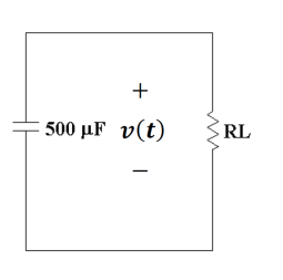
At t = t0 + 10 ms, the circuit becomes |
|||||||||||||||||||
|
|
|||||||||||||||||||
|
The time constant is |
|||||||||||||||||||
|
|
|||||||||||||||||||
|
|
|||||||||||||||||||
|
So when switch 2 is thrown we have an
effective capacitor with a voltage of 0.60 V across it that is discharging
the charges on it through the load resistor with a time constant of 0.50
s. So we know
this will follow just standard capacitor discharge. The solution is |
|||||||||||||||||||
|
|
|||||||||||||||||||
|
|||||||||||||||||||
|
|
|||||||||||||||||||
|
|
|||||||||||||||||||
|
|||||||||||||||||||
|
|